King Post Roof
Here are some roof images from our May 2016 survey. This was not the oldest roof in the house.
This King Post roof (KPR) was rather more interesting than the standard KPR we see. Most come from a time when the carpentry skills are diminishing as iron and steel fixings become more readily available. The use of such fixings also allows the truss to be built lighter, from narrower timbers, as they do not need to accommodate bulky timber joints.
It is important to realise that the King Post is holding up the middle of the tie beam, and not the tie beam supporting the KP. This allows the TB to be thinner than without a KP. Therfore the KP to TB joint is in tension and need to be well designed.
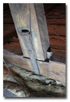
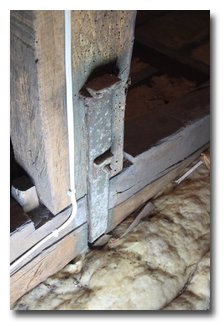
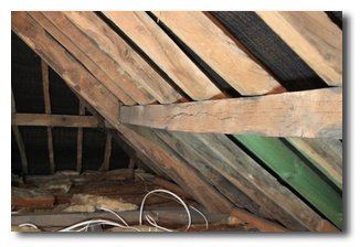
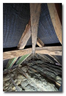
Left image is the front and right is the rear
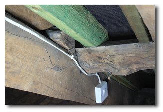
In this case the King post (KP) to Tie Beam (TB) joint is a wedged half dove tail. The wedge can be seen to the right of the post. Unusually The KP is also housed into the top of the PR. Whilst this is a standard detail the carpenter wanted to make sure the joint would not fail so it is backed up with and iron strap, with a staple at the top and a bolt lower down.
The bottom of the post is not shaped to accept struts
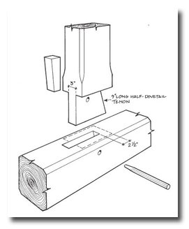
This drawing, by Jack Sorbon, clearly explains the carpentry of this joint. It's been 'borrowed' from an article on the history of American King Posts, by the American Timber Framers Guild, can be found here. American King Post Trusses This is well worth a read as it details how old the design of the KPT actually is.
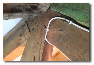
The top of the principal rafters were supported on the underside where they join the KP. It is more usual for the KP to be shaped so this is not the case
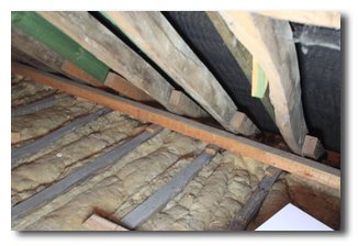
Purlins
The purlins were mounted horizontally, as opposed to the standard purlins where the top face is parallel to the surface of the roof, see left image below. Note the common rafter land on the purlin with a seat cut and a second purlin runs to the top plate. For a hip roof this has the advantage of making the purlin / hip connection a simple vertical cut instead of the more complex compound cut, below right
The purlin was mounted on the PR by way of an angled half lap, presumably nails, but top not visible, see image left
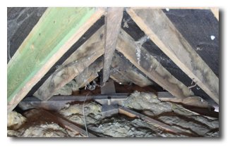
Dragon Tie and beam
The hip rafter lands on a dragon beam and tie assembly, see image left. The dragon tie runs across the corner and would be fixed into both top plates to stop them spreading. The dragon beam is jointed into the tie, with a tusk tenon and runs to the corner of the top plates.
Sprockets
A fairly standard detail in a lot of KP roofs are sprocketed rafters. They are simply short sections of rafter which reduce the angle of the roof near the eves. Other reasons for their inclusion can be to allow the exposed section of rafter to be oak when the hidden part is softwood, to extend the rafters to form an overhang on previously thatched roofs or to "throw" rain further away from the building. They can be side fixed or top fixed, in this case they are simply nailed to the side of the common rafters.
How old is it ?
As we don't have a precise date this is all open to interpretation. Technology was progressing quickly at this point in time
The "Mechanical Principles of Carpentry" of 1827 has KP trusses with straps.
The strap has a bolt & square nut, which assuming it is an interchangeable thread, would put it after around 1800 (Machine invented by Henry Maudslay 1797)
The "Carpenters New Guide" of 1848, page 67 shows a wedge bottom KP. There are also others with straps and housed posts.
The "Practical House Carpenter" of 1843, pdf page 190 shows the later detail with a vertical bolt. Also shown are Dragon ties.
More research is always needed, but the above would suggest a date Early to Mid 19C would be reasonable.